Fiat HS (7-Z0146) Project

Contents

Setup Diagram for Fiat HS Project
OEM Test: FIAT Dual Wire High Speed CAN
Specification: 7-Z0146
Transceiver: Configuration 5 DWCAN
Project: MxPLTFiatHS.zip
Note: All cable lengths should be less than 1.0 m. Signals are measured under minimum physical load conditions.
1.Open MxVDev. 2.Select File-> Open->Project from the main menu. 3.Use the Open dialog to select the project file: MxPLTFiatHS\MxPLT Sample Project Fiat.mxp 4.Click Open. 5.Click Edit Harness ( 6.In MxTransIt, click on the PLT Test Manager Transform to select it and display its Properties box. 7.Click the Launch MxPLTConversionTool verb to open the tool. 8.Select the “TestCases Generation” tab to generate Scenarios and TestCases dynamically based on selected inputs.
9.Following are the inputs for the TestCase Generation tab of the Mx‑PLT tool. a.Select TestCase Definition File. Click the browse button ( b.DUT Type. If the DUT does not have a 120-ohm termination-resistor, select "No Internal Termination". If the DUT has the internal 120-ohm termination-resistor, select "Internal Termination_120Ohms". c.Change the Baud Rate as per DUT type. d.Select the Supply Voltage Range as per DUT supported voltage ranges “Standard” (9V to 16V) or “Extended” (6V to 26.5V). e.Select Tstart-up Measurement: •Select "With Rx" to measure the start-up time between the first received message from DUT and the fault removal time. •Select "With Tx" to measure the start-up time between the first successful transmit message from PLT and the fault removal time. In this case, PLT transmits an additional TEST message (0x111) with 10 ms periodicity from just before fault removal up to 3 sec. f.Crank Communication. If DUT supports communication during cranking, select “Supported”. Otherwise, select the “Not Supported” option. g.Select Ignition Type: •Select “Input High” if DUT wakes-up with 12V – 14V on ignition line. •Select “Input Low” if DUT wakes-up with 0V on ignition line. •Select “None” if DUT wakes-up with Vbatt itself. h.Enter a valid CAN Rx Id, which is received from ECU. This Rx ID is used to trigger and display the waveform. i.Click the browse button ( 10.Click the Generate TestCases button to generate Scenarios and TestCases for a specific OEM. 11.Select “Message Configuration” tab. 12.Configured default messages are displayed. You can edit the messages as applicable based on the ECU under test. This message is used to wake up the DUT and to continue the ECU communication (BCM message). Note: Default configured messages need to be deleted if ECU wakes up with Vbatt (or) Ignition line.
13.Click on the Save Configuration button, and observe the “XML file successfully generated” message. Note: The CAN Configuration file path is the same as the MxV Project folder path selected in the “TestCase generation” tab. 14.Close the Test Conversion Tool, but leave MxVDev running. |


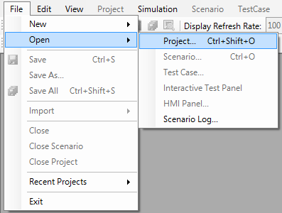
1.Open MxVDev. 2.Select File-> Open->Project from the main menu.
3.Use the Open dialog to select the project file: MxPLT Sample Project FiatHS.mxp
4.Click Open. 5.The generated Scenarios and TestCases are displayed in the Project Explorer:
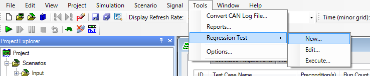
6.Select Tools->Regression Test->New.
7.Click the Add button in the Regression Command File dialog:
8.Enter User Details (Optional) in the Test Info panel. Click Next.
9.Click Next in Regression Output Wizard. 10. Click Next in Distribution List. 11. Click Next in Execution Options. 12. In Scenario Query Builder, expand the Tree for the NoInternalTermination folder. Select a Scenario (for example: "7.1.1 Recessive Output Voltage Levels.mxs") and click Next. 13. Click Finish to open the Save Regression Script dialog:
14. Save the Regression Script File (.mxreg). 15. Click the "Close and Run" button in the Regression Command File dialog:
The Regression Test Progress window shows the progress and pass/fail information of the Regression Test for the selected Scenario.
After completion of the Regression test, the report is automatically displayed. |


Test Name |
Test Description |
Observation |
|---|---|---|
7.2.1 Recessive signal voltage levels |
To measure CAN bus signal voltage level as to recessive state. |
Observe RecVCanH,RecVCanL, RecVdiff Signals for Recessive OutputVoltageLevels. Acceptance Criteria: MIN MAX RecVCanH --> 2.0V 3.0V RecVCanL --> 2.0V 3.0V RecVdiff --> -500mv +50mv |
7.2.2 Dominant signal voltage levels |
To measure CAN bus signal voltage level as to dominant state |
|
7.2.2 Domnt Sig Vtg Lvl TstCase1 |
To measure the Dominant Signal voltage levels |
Observe DomVCanH,DomVCanL, DomVdiff, DomVcm Signals Acceptance Criteria: MIN MAX DomVCanH --> 2.75V 4.5V DomVCanL --> 0.5V 2.25V DomVdiff --> 1.5V 3.0V |
7.3 Recessive Input Threshold |
To Measure the recessive input threshold of the DUT |
|
7.3 Rec InPut Thrshld 6.5V |
To Measure the recessive input threshold of the DUT,when the Voltage value of U at 6.5V |
Acceptance Criteria: Observe the DUT is not allowed to stop the transmission of its frames |
7.3 Rec InPut Thrshld -2V |
To Measure the recessive input threshold of the DUT,when the Voltage value of U at 2V |
Acceptance Criteria: Observe the DUT is not allowed to stop the transmission of its frames |
7.4 Dominant Input Threshold |
To Measure the dominant input threshold of the DUT |
|
7.4 Domnt InPut Thrshld 6.1V |
To Measure the Dominant input threshold of the DUT,when the Voltage value of U at 6.1V |
Observe DomVInpThrshld value Acceptance Criteria: The DUT shall stop the transmission of its frames. |
7.4 Domnt InPut Thrshld -2V |
To Measure the recessive input threshold of the DUT,when the Voltage value of U at -2V |
Observe DomVInpThrshld value Acceptance Criteria: The DUT shall stop the transmission of its frames. |
7.5 CAN_H and CAN_L Internal Resistance |
To measure CANH and CANL internal resistance |
|
7.5 Intrnl Resistance Scope1 U 0V |
To measure the Internal Resistance of CANH & CANL, When the voltage level of U at 0V. |
Observe RinCanH, RinCanL,deltaRin Acceptance Criteria: MIN MAX RinCanH --> 5kΩ 50KΩ RinCanL --> 5kΩ 50KΩ deltaRin --> -3 3 |
7.5 Intrnl Resistance Scope1 U 5V |
To measure the Internal Resistance of CANH & CANL, When the voltage level of U at 5V. |
Observe RinCanH, RinCanL,deltaRin Acceptance Criteria: MIN MAX RinCanH --> 5kΩ 50KΩ RinCanL --> 5kΩ 50KΩ deltaRin --> -3 3 |
7.5 Intrnl Resistance Scope2 U 5V |
To measure the Internal Resistance of CANH & CANL, When the voltage level of U at 5V. |
Observe RinCanH, RinCanL,deltaRin Acceptance Criteria: MIN MAX RinCanH --> 5kΩ 50KΩ RinCanL --> 5kΩ 50KΩ deltaRin --> -3 3 |
7.5 Intrnl Resistance Scope3 U 5V |
To measure the Internal Resistance of CANH & CANL, When the voltage level of U at 5V. |
Observe RinCanH, RinCanL,deltaRin Acceptance Criteria: MIN MAX RinCanH --> 5kΩ 50KΩ RinCanL --> 5kΩ 50KΩ deltaRin --> -3 3 |
7.6 Internal Differential Resistor |
To measure internal differential resistance of DUT. |
Observe Rdiff Acceptance Criteria: MIN MAX Rdiff --> 10kΩ 100KΩ |
7.7 Min and Max Power supply voltage level |
To define power supply voltage min. and max. level for a correct communication through bus. |
|
7.7 Pwr supply vltg lvl Extd_Min Supply Vltg |
To define power supply voltage min. for a correct communication through bus. |
Acceptance Criteria: check if DUT can transmit and receive frames within a 18 V and to 6V or 10V (depending on the supply class node) power supply voltage range. |
7.7 Pwr supply vltg lvl Extd_Resume Vltg |
To measure voltage at which communication is restored after min voltage for communication has been reached. |
|
7.7 Pwr supply vltg lvl Extd_Resume Time |
Measure the time until the DUT resumes bus communication, i.e., successful reception or transmission of a message after the power voltage has reached a level of 6.5V
|
The DUT must resume bus communication by Tstart-up ms (see system specifications) after the power voltage has reached a level of 6.5V |
7.7 Pwr supply vltg lvl Extd_Max Supply Vltg |
To measure the maximum supply voltage level for CAN communication |
Acceptance Criteria: check if DUT can transmit and receive frames within a 18 V and to 6V or 10V
|
7.7 Pwr supply vltg lvl Std_Min Supply Vltg |
To define power supply voltage min. for a correct communication through bus. |
Acceptance Criteria: check if DUT can transmit and receive frames within a 18 V and to 6V or 10V
|
7.7 Pwr supply vltg lvl Std_Resume Vltg |
To measure voltage at which communication is restored after min voltage for communication has been reached. |
|
7.7 Pwr supply vltg lvl Std_Resume Time |
Measure the time until the DUT resumes bus communication, i.e., successful reception or transmission of a message after the power voltage has reached a level of 9V
|
The DUT must resume bus communication by Tstart-up ms (see system specifications) after the power voltage has reached a level of 6.5V |
7.7 Pwr supply vltg lvl Std_Max Supply Vltg |
To measure the maximum supply voltage level for CAN communication |
Acceptance Criteria: check if DUT can transmit and receive frames within a 18 V and to 6V or 10V
|
7.8 Engine start-up voltage curve |
To check if start-up procedure is performed correctly at voltage drop |
|
7.8 Comm during Crank Supported |
To check if start-up procedure is performed correctly at voltage drop |
Acceptance Criteria: The DUT must resume bus communication by Tstart-up ms (see system specifications) after the power voltage has reached a level of 6.5V |
7.8 Comm during Crank Not Supported |
To check if start-up procedure is performed correctly at voltage drop |
Acceptance Criteria: The DUT must resume bus communication by Tstart-up ms (see system specifications) after the power voltage has reached a level of 10.5V |
7.9 Bit Rise and Fall times |
To Measure the recessive-to-dominant and dominant-to-recessive transition times of the CAN signal. |
|
7.9 Bit Rise and Fall Time Min Load |
To measure the Signal Fall time of the DUT CAN bus signal between 10 % and 90 % of Vdiff with min Load. |
Acceptance Criteria: Min Max Trise 50 2000 Tfall 50 4000 |
7.9 Bit Rise and Fall Time Max Load |
To measure the Signal Fall time of the DUT CAN bus signal between 10 % and 90 % of Vdiff with max Load. |
Acceptance Criteria: Min Max Trise 50 2000 Tfall 50 4000 |
7.10 Signal Characteristics |
To check symmetry for both CAN bus signal under different load conditions. |
|
7.10 Signal Char Symmetric Min Load |
To check symmetry for both CAN bus signal under Minimum load conditions. |
Acceptance Criteria: No asymmetric performances/oscillations are present – In the first half of bit time, bus output level to be within 81% and 150% of d.c. valuate at bit fall – In the second half of bit time, bus output level to be within 95% and 105% of d.c. valuate at bit fall. |
7.10 Signal Char Symmetric Max Load |
To check symmetry for both CAN bus signal under Maximum load conditions. |
Acceptance Criteria: No asymmetric performances/oscillations are present – In the first half of bit time, bus output level to be within 81% and 150% of d.c. valuate at bit fall – In the second half of bit time, bus output level to be within 95% and 105% of d.c. valuate at bit fall. |
7.11 Time bit accuracy at message transmission |
To define time bit accuracy at DUT message transmission Note: The configured message should have maximum DLC and also fixed data bytes value as per specification. |
|
7.11 Time bit accuracy during msg tx |
To define time bit accuracy at DUT message transmission |
Acceptance Criteria: Check that oscillator deviation and time bit deviation are within prescribed value and less than +/-0.3%. |
7.12 Immunity test to potential mass deviations |
To define immunity test to potential ground deviations. |
|
7.12.2 Immunity Tst To Potential Mass Dev Mthod 1 |
Expose the DUT to ground offset levels of 4.5 V maximum. |
Acceptance Criteria: Measure the ground deviation value where the first error frame occurs.
Min Max VOffstCommErr 0 4.5 |
7.12.3 Immunity Tst To Potential Mass Dev Mthod 2 |
Expose the DUT to ground offset levels of 4.5 V maximum. |
Acceptance Criteria: Measure the ground deviation value where the first error frame occurs.
Min Max VOffstCommErr 0 4.5 |
7.13.1 Immunity test to Power Drop |
To define DUT immunity to power loss |
|
7.13.1 Immunity test to Power Drop |
To define DUT immunity to power loss |
Acceptance Criteria: As soon as power supply is restored, standard operation shall be recovered automatically within Tstart-up ms |
7.13.2 LOG immunity test (ground drop) |
To define DUT immunity to ground loss. |
|
7.13.2 LOG immunity test (ground drop) |
To define DUT immunity to ground loss. |
Acceptance Criteria: As soon as ground connection is restored, standard operation shall be recovered automatically within Tstart-up ms |
7.13.3 Immunity Test Of CAN_H and CAN_L Interruption |
To define DUT immunity at CANH and/or CANL interruption. |
|
7.13.3 Immunity Test Of CAN_H Interruption |
To define DUT immunity at CANH interruption. |
Acceptance Criteria: As soon as the trouble is cleared, standard operation shall be recovered automatically within Tstart-up ms |
7.13.3 Immunity Test Of CAN_L Interruption |
To define DUT immunity at CANL interruption. |
|
7.13.4 Immunity test at short to battery of CAN_H and CAN_L |
To define DUT immunity at CANH and/or CANL interruption. |
|
7.13.4 CAN_H shrt To 18V |
To Monitor the behavior of the DUT when CANH short to supply of 18V. |
Acceptance Criteria: As soon as the trouble is cleared, standard operation shall be recovered automatically within Tstart-up ms |
7.13.4 CAN_L shrt To 18V |
To Monitor the behavior of the DUT when CANL short to supply of 18V. |
Acceptance Criteria: As soon as the trouble is cleared, standard operation shall be recovered automatically within Tstart-up ms |
7.13.4 CAN_H shrt To 26.5V |
To Monitor the behavior of the DUT when CANH short to supply of 26.5V. |
Acceptance Criteria: As soon as the trouble is cleared, standard operation shall be recovered automatically within Tstart-up ms |
7.13.4 CAN_L shrt To 26.5V |
To Monitor the behavior of the DUT when CANH short to supply of 26.5V. |
Acceptance Criteria: As soon as the trouble is cleared, standard operation shall be recovered automatically within Tstart-up ms |
7.13.5 Immunity Test At Short To Ground Of CAN_H and CAN_L |
To define DUT immunity at CANH and/or CANL short to ground |
|
7.13.5 CAN_H shrt To Gnd |
To Monitor the behavior of the DUT when CANH short to GND. |
Acceptance Criteria: As soon as the trouble is cleared, standard operation shall be recovered automatically within Tstart-up ms |
7.13.5 CAN_L shrt To Gnd |
To Monitor the behavior of the DUT when CANH short to GND. |
Acceptance Criteria: As soon as the trouble is cleared, standard operation shall be recovered automatically within Tstart-up ms |
7.13.6 Immunity Test At Short Of CAN_H To CAN_L |
To define DUT immunity at CANH short to CANL |
|
7.13.6 Shrt between CAN wires |
To Monitor the behavior of the DUT when CANH & CanL are shorted . |
Acceptance criteria: As soon as the trouble is cleared, standard operation shall be recovered automatically within Tstart-up ms |