GMW14241 SWCAN Project

Contents

Setup Diagram for the GMW14241 SWCAN Project
OEM Test: GM Single Wire Low Speed CAN
Specification: GMW14241 Sec 4.3
Transceiver: Configuration 3 SWCAN
Project: MxPLTGMSWCAN.zip
1.Open Mx‑VDev. 2.Select File-> Open->Project from the main menu. 3.Use the Open dialog to select the project file: MxPLT Sample Project GM.mxp 4.Click Open. 5.Click Edit Harness ( 6.In Mx‑TransIt, click on the PLT Test Manager Transform to select it and display its Properties box. 7.Click the “Launch MxPLTConversionTool” Verb to open the tool. 8.Select the “TestCase Generation” tab to generate Scenarios and TestCases dynamically based on selected inputs.
9.Following are the inputs for the TestCase Generation tab of the Mx‑PLT tool. a.Select TestCase Definition File. Click the browse button ( b.Bus Interface. Select SWCAN. c.Select the Baud Rate as per DUT type. d.Select the Supply Voltage Range. Either “Standard” (9V to 16V) or “Extended” (6V to 26.5V). e.Crank Communication. If the DUT supports communication during cranking, select Supported. Otherwise select the Not Supported option. f.Select the “Load Resistor” supported by the DUT. g.Enter a valid CAN Rx Id, which is received from ECU, this Rx id is used to trigger and display the waveform. h.Enter a valid Diagnostic Response Id, configured USDT for the DUT. i.Click the browse button ( 10.Click the Generate TestCases button to generate Scenarios and TestCases for a specific OEM. 11.Select the Message Configuration tab. 12.Configured default messages are displayed. You can edit the messages as applicable based on the ECU under test. This message used to wake up the DUT and to continue the ECU communication (BCM message).
13.Click the “Save Configuration” button. Observe the “XML file successfully generated” status message. Note: The CAN Configuration file path is same as the MxV Project folder path selected in the “TestCase Generation” tab. Close the Test Conversion Tool, but leave MxVDev running. |


1.Open Mx‑VDev. 2.Select File-> Open-> Project from the main menu.
3.Use the Open dialog to select one of the following project files: •64 bit: C:\Program Files (x86)\MicroMax\MxSuite 3.xx.xx.xxxxx\Samples\MxPLTGMSWCAN\MxPLT Sample Project GM SWCAN.mxp •32 bit: C:\Program Files\MicroMax\MxSuite 3.xx.xx.xxxxx\Samples\MxPLTGMSWCAN\MxPLT Sample Project GM SWCAN.mxp 4.Click Open. 5.The generated Scenarios and TestCases are displayed in the Project Explorer:
6.Select Tools-> Regression Test ->New.
7.Click the Add button in the Regression Command File dialog:
8.Enter User Details (Optional) in Test Info panel. Click Next.
9.Click Next in Regression Output Wizard. 10. Click Next in Distribution List. 11. Click Next in Execution Options. 12. In Scenario Query Builder, expand the tree for the NoInternalTermination folder. Select a Scenario (for example:"4.1.1.1 RecessiveOutputVoltageLevels.mxs") and click Next.
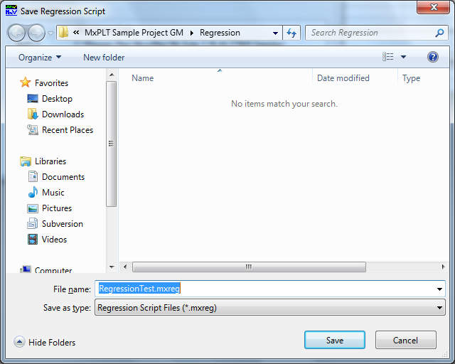
13. Click Finish to open the Save Regression Script dialog:
14. Save the Regression Script File (.mxreg). 15. Click the Close and Run button in the Regression Command File dialog:
The Regression Test Progress window shows the progress and pass/fail information of Regression Test for the selected Scenario.
After completion of the Regression Test, the report is automatically displayed.
|


GMW14241 SWCAN TestCases