LVT Power Supply

Contents
LVT VBS Transform
Prerequisites:
•Installed LVTGO-VBS software
•Installed ADD2 COMM Dongle Drivers included in LVTGO-VBS
•Password (unlock code) for LVT installation

This Transform is used to test the LVTGO-VBS (Real Time Voltage disturbance and ground offset simulator).
Set values for the following properties:
Tick Period – Enter the Tick Period in seconds. This specifies periodic rate at which the Transform is invoked or 'ticked'.

Notes:
1.The LVT VBS Device Transform has one inport, LvtMessageIn. All referenced values and return values of supported lvtscript functions act as outports. For example:
•GetCurrentCycle -> Get the current cycle number from the LVT hardware.
Return value -> cycle number (acts as outport in LVT VBS Device named as LvtCyclenumber)
•GetHILReadings ->Get the HIL input readings
Return value -> void
Parameters ->
dHILValues (reference variable): act as outports in LVT VBS Device named as LvtdHILValues
bHILValues (reference variable): act as outports in LVT VBS Device named as LvtbHILValues.
2.LvtMessageIn is a message type Signal. User can call lvtscript functions by selecting the function name from the SelectFunctionId combo box in LvtMessageIn Signal.
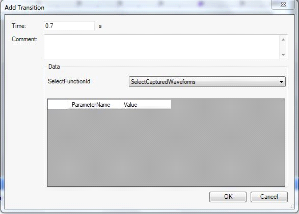
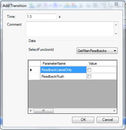
To select parameters:
Double-click on the LvtMessageIn Signal to create a transition and configure the values.

3.VOut is a continuous type Signal used to change the Output Voltage of the LVT.
4.VGndOffset is a continuous type Signal used to change the Ground Offset Voltage of the LVT.
To test the LVT VBS Transform
1.Power up the LVT unit.

2.Select All Programs->add2->LVTEST VISUALCONNX Application V6->LVTEST 6 from the Windows Start menu.

3.Select “Settings” from the Connections menu.

4. On the “CAN Interface Hardware” panel, click the Configure button.

5. In the Hardware panel, select “ADD2 DONGLE” from the drop-down list and click on “Apply”.
6.Set the CAN CHANNEL, Baud Rate, and Sample Point.
7.Uncheck the “Triple Sample” checkbox and click OK.
8.Uncheck the “Show this settings dialog before connecting to target” checkbox.
9.Press OK and click Run.
10. Click the “Captured Waveforms” button and the “Configure and Run Test” button.


11.Go to the “Captured Transfer” tab and click the “Connect and sync” button.

12. Open the MxVDev Project for LVT and run the TestCases and Scenarios.
13. After completion of all tests, click the Stop button of the LVTEST VISUALCONNX application.
Example: Creating Crank Waveforms using the LVT VBS Transform
1. Create a TestCase.
2. Select the LvtMessageIn Signal and insert transitions.

3.Transitions should be in the order shown below:
a.SelectFunctionId -> ResetWaveformCounter

b. SelectFunctionId -> SetGlobalConstraints. (Enter the required value for parameters MaxU and FinalU.)

c. SelectFunctionId -> ChooseCapturedWaveformsDir. (Enter the DirPath in sDirPath where all captured waveforms are stored.)

d. SelectFunctionId -> LoadCapturedWaveformsListFile. (Enter the waveform file path in filepath.)

e. SelectFunctionId -> StoreListedCapturedWaveformsOnLVT (Enter the waveform file path in sListPath.)

f. SelectFunctionId -> SetCapturedWaveformIndex. (Enter the value for waveIndex.)

g. SelectFunctionId -> PlayWaveform

Functions Supported by the LVT VBS Transform
1.ChooseCapturedWaveformsDir(sDirPath)
2.ClearLog()
3.ConfigureAnalogueOutputTrigger(WhichTrigger,Enabled,OffsetHigh,IsNegativeHigh,
StepHigh,OffsetLow,IsNegativeLow,StepLow)
4.ConfigureOutputTrigger(OutputTriggerType,Offset,IsNegative,AnchorStep,PulseWidth,
CANID,IsExtended,CANMessageBytes,CANMessageArray)
5.DeleteAllCapturedWaveformsFromLVT()
6.DeleteSelectedCapturedWaveformsFromLVT(IndexList)
7.DisplayPreview(Visible)
8.DisplayTestForm()
9.DisplayTransferForm()
10.DisplayWaveformMainForm()
11.EnableConfigurationTrigger(UseTrigger)
12.GetCurrentCycle()
13.GetCurrentStep()
14.GetHILReadings(dHILValues,bHILValues)
15.GetMainReadbacks(SampleInterval,ReadbackValues,LatestOnly,Flush)
16.GetWaveformParameters(lCycleNum,ByRef Uvalues,ByRef Tvalues,ByRef FValues,LatestOnly,Flush)
17.IsCurrentlyConnected()
18.LoadAllCapturedWaveformsFromLVT()
19.LoadCapturedWaveformsListFile(FilePath)
20.LoadProfile(sProfileName)
21.LoadSelectedCapturedWaveformsFromLVT(IndexList)
22.PauseWaveform()
23.PlayWaveform(ErrorAcceptanceLevel,ByRef ReturnString)
24.ReadyToConfigureCycle(CycleNumber,ShouldWait)
25.ResetWaveformCounter()
26.SaveLog()
27.SelectCapturedWaveforms()
28.SendConfigurationTrigger(TriggerOn)
29.SetVoltageSettings(UNumber,enDistributionType,ActualOrMinVolts,MaximumVolts,MeanVolts,ResolutionVolts,SeedNumber)
30.SetCapturedWaveformIndex(WaveIndex)
31.SetFastOutput(SetOn)
32.SetFrequencySettings(FNumber,enDistributionType,ActualOrMinFrequency,MaximumFrequency,MeanFrequency,ResolutionFrequency,SeedNumber)
33.SetGlobalConstraints(MaxU,FinalU)
34.SetGOSmoothingMode(nMode)
35.SetGroundOffset(GroundOffset)
36.SetInputTriggerType(UseTriggerSource,UseTriggerMode)
37.SetLVTCOMVerbosityLevel(iLevel)
38.SetMicroCutoutSpecificSettings(StepLength,TimeUnit,FirstCount,LastCount,PulseType,PulseHigh)
39.SetNumCycles(NumCycles)
40.SetOutputFilterMode(Mode)
41.SetParameterStreaming(Value)
42.SetStartCycle(CycleNumber)
43.StopLogging()
44.StopWaveform()
45.StoreListedCapturedWaveformsOnLVT(sListPath)