Pass/Fail Algorithms

Contents
We call a sequence of changes in a Signal a pattern. When we create a TestCase, we create the Expected Behavior Patterns. When we run a test, we measure the Actual Behavior Patterns. The algorithm for judging pass/fail looks for a match between the expected pattern and the actual pattern. This is called pattern matching. If you use Variant DataBlocks, there may be multiple patterns.
Here are some general rules about Pattern Matching: •The Pass/Fail tests are dependent on the type/classification of the Signal. By default, Discrete Signals use the Discrete Pass/Fail algorithm and Continuous Signals use the Continuous algorithm, however his can be changed in the Signal Properties. •In the MxSuite, a change in a Signal is captured in a transition. A transition has two components: a time and a value. •You can specify a Tolerance to both the time and value components of expected result transitions. •To determine pass or fail, we compare the expected transitions with the actual transitions. •For a measurement instrument which periodically samples, we don’t know what value a Signal has between the samples; we have rules for interpolation. •When analyzing for pass or fail, we always search forward in time. This means that a test failure point will be at or before the point that MxVDev recognizes that a failure exists. •For numeric Signals: oIf two or more sequential transitions have the same value, then only the first transition is considered. oA Signal is steady at the value specified in a transition until we receive the next transition. |
Signals that can take a limited number of integer values are classified as Discrete. A typical example is the transmission state PRNDL. Tolerances are specified as follows: •For each transition, the transition time must be within the Time Tolerance, and transition value within the Value Tolerance. The edges of the Tolerance Rectangles (as shown below) are the positive and negative value tolerance (vertical) and the positive and negative time tolerance (horizontal). •Transitions must be in order, even if the Time Tolerances would allow them to be swapped. •If the Transition Count tolerance is zero, there must be exactly one Actual transition for every Expected transition. •If the Transition Count tolerance is non-zero, then starting at the beginning of the test all transitions must match as follows: oIf there are fewer Actual Transitions than expected, but the number missing is within the Negative Count Tolerance, then the test passes. oIf there are more Actual Transitions than expected, and the additional tolerances are within the Positive Count Tolerance, then the test passes. (Note this case is not a common condition to test for, but it can be used, for example, to specify that a Signal must change a certain number of times in a certain period.)
|

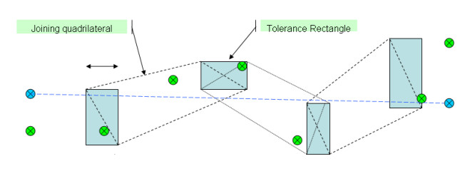
Continuous Signals (both fixed and floating) are used to represent data such as temperature, rpm, or wheel speed. The pass/fail analysis looks for the lines joining actual transitions to cross tolerance envelope boundaries (shown in dotted lines below). •The edges of the Tolerance Rectangles (as shown below) are the positive and negative value tolerance (vertical) and the positive and negative time tolerance (horizontal). •All transition time/value points, and the interpolating lines, must stay within external envelope defined by the tolerance rectangles and the joining quadrilaterals. •There can be any number of actual transitions. •Before the first Expected Transition and after the last Expected Transition no pass/fail testing is performed. •In the example below, both green and blue Actual Transition markers would result in a pass. Continuous Signal Test Pass Example
Continuous Signal Test Failure Example
|

For pass/fail analysis, the judgment algorithm scans the Actual Message Transitions, comparing them with the Specified Message Transitions as it goes. Here are the comparison rules: Pass/Fail Rules: •There must be exactly one Actual Transition for every Expected Transition. •For each Transition, you can define a mask to specify which bits you want to compare and which bits you want to ignore. See the section below on masks. •For the bits you decide to test, ALL Actual Bits must match the corresponding Expected Bits. •There are no Value Tolerances (as are found for Continuous Signals). •By default, transitions must be in order, even if the Time Tolerances allow them to be swapped. There is an option checkbox Ignore Message Order. If this is checked, the messages can arrive in any order, as long as the Actual Message is within the Time Tolerance of the Expected Message. •You can define Signals within Messages. These Signals are tested separately for Pass/Fail if they are included in the TestCase. These Signals can have Value Tolerances Masks: The Pass/Fail Judgment algorithm compares Actual and Expected messages, but only where corresponding bits in the Mask are set to one. You can define Masks in a couple of ways: Default Mask (using Signal Dictionary settings)
•Defined Fields - The Mask is created such that only defined fields are tested. The mask is set to zero for all other bits that are not included in defined fields. oThis is useful, for example, when you define CAN messages (or import a DBC file). In this case you are likely not interested in the values of the message bits that are outside the defined fields. oThis is the default setting when importing DBC or LDF files. •Every Bit - The Mask will be all FF's, so that every bit is tested. oThis useful if you want to define fields, but you are also interested the value of every bit of the full message. oThis is the default setting (but see above). Custom Mask: For each Expected Transition you can explicitly define a Custom Mask for that Transition. 1.Double-click on the Transition. 2.Select the Message Raw Data tab. 3.Select Custom Mask, and set an explicit mask in the Pass Fail Mask panel (see below).
|

