NI VeriStand
The NI VeriStand Transform interfaces to a custom device. The Transform enables you to deliver stimulus Signals from MxVDev TestCases onto the Real-Time processor card and capture response data back to MxVDev on the PC.
•Danlaw provides a custom device for VeriStand and the MxNet DLL that runs in the VeriStand Real-Time environment.
•The VeriStand sample project has the custom device added with 2 inputs and 2 outputs. Inputs are connected to outputs for a loop-back test.
•A UDP connection is established between the Transform and the MxNet DLL. Test data is streamed over this connection.
•NI VeriStand 2011 or higher (must be installed on RT as well) •MxSuite 3.36.17.26140 or higher Note: Registration is required for downloads from the Danlaw server. oFor Veristand 2013 and higher, click here to open the download folder: ▪MxVDev project: VeriStand_MxV_prj.zip ▪VeriStand project: Engine_Demo.zip
|
1.Unzip (extract) the Custom Device file into the appropriate VeriStand Custom Devices folder. Change the year to the version you are using, for example: •C:\Users\Public\Public Documents\National Instruments\NI VeriStand 2016\Custom Devices\MxSuite Connector\ 2.Find MxNetVeristand.dll in the MxSuite installation folder, for example: C:\Program Files\MicroMax\MxSuite 3.36.45.28551\Harness\MxNet\Veristand\MxNetVeristand.dll 3.Copy the file to the appropriate VeriStand Program files folder. Change the year to the version you are using, for example: •C:\Program Files (x86)\National Instruments\VeriStand 2016\MxNetVeristand.dll 4.Use FTP to transfer MxNetVeristand.dll to the c:\ni-rt\system folder on the RT target system. 5.Start MxVDev and open the MxVDev project. (If you are using a sample project, open MxV.mxp from either SampleProject1.0.zip or VeriStand MxV prj.zip.) 6.Click 7.Click on the VeriStand Transform to select it and display its Properties box. 8.Note the value of the Server Port property.
9.Use the VeriStand System Explorer to set the UDP port to the same one as in MxTransit. The default is 5481.
10.In MxTransIt, set the IP or Server Name property to the IP address of the system where it is deployed: either the IP of the same Windows PC or the IP of the RT target system.
11.Click the Deploy button to deploy the VeriStand project. Refer to NI VeriStand documentation for details.
Note: To rename a port in VeriStand System Explorer, click on the port and type in a new name. Model ParametersIf the VeriStand Project contains the model with parameters that need to be changed during the test, configure the VeriStand Transform in MxTransIt. For this the VeriStand Project needs to be loaded and running in parallel with MxSuite. MxSuite connects to the Workspace API to get the list of parameters and to write to parameters. In MxTransIt: change the Target Name to match the name in System Explorer (for example “Controller”) and set the ‘Use Parameters’ property to true. Then when the VeriStand project is deployed and running, click the ‘Enumerate’ verb link. This will enumerate all stimulus and response ports from the system as well as model parameters. |
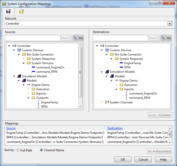
The sample project performs a loop back test to demonstrate and test your system. 1.Follow the Setup procedure above. 2.Download the sample project. See Prerequisites. 3.Create a project folder on your PC. We recommend a folder under your Users folder, such as: C:\Users\MyUserName\MyMxVProjects\MxVeriStandSample 4.Unzip (extract) the downloaded file into the project folder. 5.Start MxVDev and open the project file: MxV.mxp 6.Open Test Scenario and click The figures below show the mappings in the VeriStand sample projects. The mappings dialog is in the System Explorer under Tools->Edit Mappings. Inputs are connected to outputs for a loop-back test:  System Configuration Mappings for the Mx‑Suite Connector 2.0 Sample Project (used with VeriStand 2011)  System Configuration Mappings for the Engine Demo Sample Project (used with VeriStand 2013) |
To import channel data from a CSV file, right-click on the device name or click on the command in the toolbar.
The format of the CSV file is the same as CSV to DataDictionary Example.csv. You can use the same file to import data into VeriStand and into the MxVDev Signal Dictionary. Notes: •If a line starts with semicolon (;) it is a comment, and is ignored. •Not all fields need to be filled in, but a comma is required for each column. •VeriStand uses only ‘Classification’, ‘Name’ and ‘Data Flow’ – so both inputs and outputs can be specified in one file. •You can also specify other Signal info which is used in the MxVDev Signal Dictionary (such as Min, Max, and Initial Value). •You only need numeric Signals, since that is what VeriStand expects. |
When the Custom Device is connected to a stimulus port, that port is not available for other purposes, such as buttons and dials in the VeriStand workspace. You can use pass-through channels instead. For every Stimulus channel you add, the system automatically adds a response channel with “_Ctrl” appended. You can use this channel in your workspace. When MxSuite is not connected, it acts as a direct pass-through by passing that value through to corresponding port. When MxSuite is running and in control of the system, the pass-through channels disconnect and don’t do anything. By default, the ports on the VeriStand Transform are hidden. Use the Hide '_Ctrl' ports property to display them.
Note: This feature requires Custom Device MxSuite Connector 2014 v2 or newer. Download here. |
To remove the custom device: 1.Open the VeriStand System Explorer. 2.Select the relevant MxSuite Connector. 3.Click the remove button located in the toolbar at the top of the window.
|
Create an Empty VeriStand project and try to deploy it to the RT system. If there are any issues with the empty project, they must be resolved through VeriStand help or NI support. |


