CAN Transmit Driver

Contents

Use this Transform to transmit Signal information onto a CAN bus. The Transform uses the DBC file to create and transmit the messages. It supports standard CAN and CAN FD.
Basic Configuration
1.Click ![]() in the CAN Database property to display the CAN Bus Configuration form.
in the CAN Database property to display the CAN Bus Configuration form.

Click to expand.
2.Select the Database Type: ARXML or DBC
3.Use the Add button to select one or more database files.
4.If you are using ARXML files, select the network you are testing from the Selected Network drop-down list.
5.Select one or more nodes and messages to Simulate and Transmit for. If you select individual messages, only the selected messages are transmitted.
Note: If you select a node to be simulated by this Transform, be sure that the same node is not simulated by MxVDev. See Network Configuration. Selecting a node in both places can result in duplicate messages on the bus.
6.Click OK. The signals used by the selected nodes become inports on the Transform.
7.Use the Transform's Name property to change the port names to the name of the CAN bus. If you are using the CAN bus from MxVDev, then the name should match the name of the CAN bus used in Network Configuration there.
 |
8.Export the ports to be used in MxVDev.
Example
The figure below shows a very simple example of a closed-loop node. The CAN Receive Driver reads a value from the CANB bus, the C# Snippet does simple signal processing, and the CAN Transmit Driver transmits a new value back to the bus.
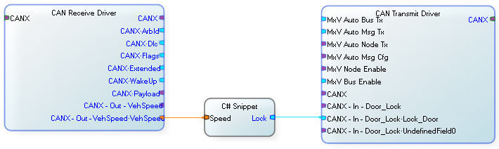
This C# Snippet is effectively simulating an ECU attached to the bus. In a more complex system, the ECU could be simulated by any of the following:
•C# Snippet
•SIL Easy
•MxVMC
•Custom Transform
•Simulink
For a step-by-step example, see Putting a Signal on a CAN Bus.
To connect the MxV Bus Enable or the MxV Auto Bus Tx port to a TestCase, you must route the Signal through the router Transforms described below. Do not export the ports on the Transmit Driver Transform.
The MxV Bus Enable port accepts a Boolean input. A value of 1 enables the bus; 0 disables it. By default, the bus in enabled. To use this port with the MxV Bus Enable System Signal, which is a message, route it through the MxV Bus Enable Router Transform.
The MxV Auto Bus Tx port accepts a Boolean input. A value of 1 enables automatic message transmission on the bus; 0 disables it. To use this port with the MxV Auto Bus Tx System Signal, which is a message, route it through the MxV Auto Bus Tx Router Transform.
To use more than one CAN Transmit Driver, use PassThru Transforms to connect the other bus control ports (MxV Auto Msg Tx, MxV Auto Node Tx, MxV Auto Msg Cfg, or MxV Node Enable) to TestCases in MxVDev. Export the inport on the PassThru Transform. Do not export the ports on the CAN Transmit Drivers.
This example shows the appropriate Signal router Transforms so that when the Signals on the Pass Thru are exported they connect correctly to the MxV system signals. The Pass Thru is not required, but it enables exporting all the ports from a single Transform.
|

This example shows how the Signal routers should be used when multiple networks are present. (This is the primary purpose of the router Transforms.) You only have one set of the bus control system Signals exported, and then they are routed either directly or indirectly to all of the networks in the harness.
|

This example shows a full CAN network harness. The Pass Thru is not required, but it enables exporting all the ports from a single Transform. The router Transforms, MxV Auto Bus Tx and MxV Bus Enable, enable the bus control ports to be exported for use in a TestCase. The CAN Transmit Driver receives Bus Control Signals from TestCases indirectly through the PassThru Transform. The ports on the Transmit Driver are not exported. Note that in this example, there are no data ports on this Transform. Signals from the CAN Transmit Driver and the Vector Device Interface are routed through the Virtual Bus Transform to enable the Virtual Bus Monitor. The Vector Device Interface transmits and receives messages from the virtual bus to a hardware bus. Other Device Interface Transforms can be used. The CAN Receive Driver reads messages from the hardware bus via the Vector Device Interface. The messages are decoded into component Signals which are available on the Transform's outports.
|

Automatic Message Transmission