MOST Transmit Driver

Contents
The MOST Transmit Driver Transform transmits MOST Signals to a MOST bus using the K2L Automotive Test System (ATS). You can use the Signals to transmit information to a connected bench or to a simulated FBlock.

Select the MOST Transmit Driver Transform from the MxTransIt Toolbox.
Configuring the Transform—Loading the MOST XML Catalog and the K2L MAG Generated DLL File
Use this procedure to configure the MOST Transmit Driver Transform:
1.In the MOST Transform's Select K2L Generated dll File property, click on the browse button (![]() ) to display the MOST Transmit Signals form.
) to display the MOST Transmit Signals form.

2.For Select MOST Catalog Xml Path, click the Add button to open the file open dialog.
3.In the file open dialog, browse to the location where MOST catalog .xml files (such as GIS361Function.xml) are stored.
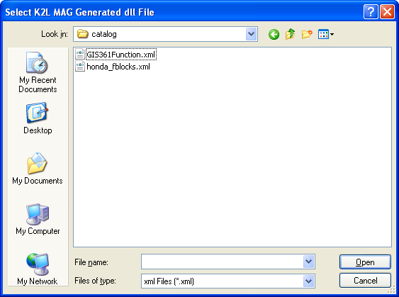
4.Select the appropriate XML file and click Open.
The catalog path is listed in the Select MOST Catalog Xml Path box.
5.For Select MOST Function Dll Path, click the Add button to open the file open dialog.

6.In the file open dialog, browse to the location where K2L MAG Generated .dll files (such as GIS361Function.dll) are stored.

7.Select the appropriate dll file and click Open.
The dll path is listed in the Select MOST Function Dll Path list.

8.Click on the Load button to load all Fblocks.

9.In the Select column, select the Fblocks that you want to be connected and used for transmission.
10.You can also set the corresponding Instance Ids in the Instance Id column. If these Signals are not selected, the Instance Id is 1. The Destination Id and the Source Id are the default node address.
11.In the Destination Id column, if you don’t specify any Destination Id, the tool will connect to Fblocks on simulated Fblocks. Otherwise it will connect to MOST bus. So specify as per requirements.
12.Click OK to generate ports for the Transform.
All Inports for the selected Fblocks are automatically generated on the Most Transmit Driver Transform.

Since it is a Transmit Transform, all ports are inports.
Ports are labeled with the format: TransformTypeInstanceId_FBlock_Function_OpType_PrimaryParamater
where TransformType can be Tx, Rx or Fb.
For example: Tx2_Amplifier_SinkName_Get_SinkNr
Note: If the Instance Id is 1, the InstanceId field does not appear in the Signal name.
If the port name is Tx_Amplifier_SinkName_Get_SinkNr:
TransformType |
= |
Tx |
InstanceId |
= |
1 |
FBlock |
= |
Amplifier |
Function |
= |
SinkName |
OpType |
= |
Get |
Primaryparameter |
= |
SinkNr |
The PrimaryParameter may or may not present for some OpTypes.
14.Right-click on the Transform and select Export Ports.
15.Select Signals to export and click OK.

16.Click (![]() ) to save the Harness.
) to save the Harness.
Creating a TestCase
1.Configure the Transform by selecting the required Fblocks to transmit and to test.
2.In MxVDev, create a TestCase and use the Pick Signals dialog to select Signals.
Note: Since this is a transmit driver Transform, all Signals are of type Stimulus.
To create a transition on a Signal, double-click in the plot area of the Signal or right-click and select Insert Transition.
For discrete Signals, see Editing Test Patterns. |
1.Message signals are MOST stream types. You can add a stream Signal transition by double clicking in the Signal's plot area. A dialog box appears that you can use to enter all stream parameters.
2.After setting all parameters, click OK. A transition is created in the TestCase plot area, which looks like this:
|


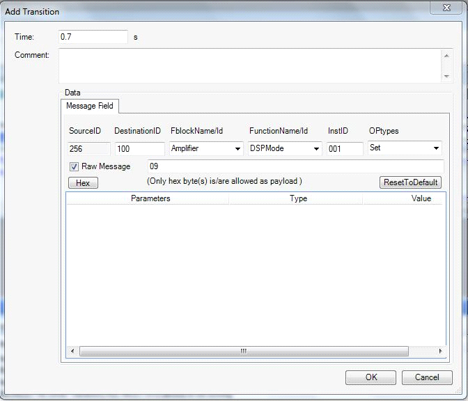
Use the Tx_RawMessage Signal to transmit a raw message. Double-click on the plot line to open the Add Transition dialog box: There are several ways to enter raw message data:
Notes: 1.The DestinationID, FblockName/Id, InstID, FunctionName/ID, and OpType fields may be either hex or decimal. 2.If the Raw Message check box is selected, all payload values should be in hex byte format. |


Related Topics: