MxDSRC

Contents

The MxDSRC is a separately-priced hardware and software system that uses the MxSuite to test DSRC components and protocols. The system provides tests as described in these documents:
https://github.com/certificationoperatingcouncil

The following test procedures are supported:
•IEEE 802.11: 80211_TSS_TP_Test_Specification
•IEEE 1609.2: CVNGSE_WAVESEC_TSS_TP_Test_Specification
•IEEE 1609.3: CVNGSE_WAVENS_TSS_TP_Test_Specification
•IEEE 1609.4: 16094_TSS_TP_Test_Specification
•SAE J2945/1: J2945_1_TSS_TP_Test_Specification
For details on your specific test, see below.
For detailed information on 802.11 tests, refer to the 80211_TSS_TP_Test_Specification. The section numbers below refer to this specification.
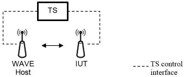
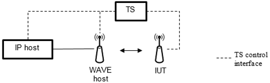
1.Power on the hardware and wait 30 minutes for the temperature to stabilize. 3.Determine the cable path losses. 4.Select the Test Configuration (hardware) for the test you are running, for example: TC4. See the tables in section 6.2. The configuration diagrams are also provided below. 5.In MxVDev, open the DSRCPhysicalLayerTestAutomation.mxp project. 6.Open MxTransIt. 7.Ensure the UDP Configuration properties on the two UDP (Generic Transform) Transforms are set correctly. For details, see: Setting the IP Addresses and Ports.  Click to expand. 8.Copy the Resource Names from the NI Measurement & Automation Explorer (NI Max) to the property on the corresponding Transforms listed here:
 NI MAX. Click to expand.
9.Ensure that the Configuration Files Folder Path property for the DSRC Physical Layer Test Manager Transform is set to the Configuration Files subfolder of the project folder as shown below. This is the location of the TDMS configuration files.  Click to expand. 10.In the Properties box of the SUT Interface Transform, enter the TCI version as shown here:
11.In MxVDev, open the Project Settings and select the tags for Channel and DataRate that you wish to test. oRxPowerStepSize is the step size as described in TP-80211-RXT-PHY-BV-05 of the document WAVE802.11-TSS&TP. Enable this tag when you need to use the values of step size defined in the Constants & Calibrations menu. When unchecked, a default step size of 2 will be used. oMaxRxPower is the maximum power level described in TP-80211-RXT-PHY-BV-05 in the document WAVE802.11-TSS&TP. Along with MinRxPower, it defines the range of power levels over which TP-80211-RXT-PHY-BV-05 is tested. Use only when Debugging. The default value is -30 dBm. oMinRxPower is the minimum power level described in TP-80211-RXT-PHY-BV-05 in the document WAVE802.11-TSS&TP. Along with MaxRxPower, it defines the range of power levels over which TP-80211-RXT-PHY-BV-05 is tested. Use only when Debugging. The default value is determined based on the Receive Sensitivity Table defined in WAVE802.11-TSS&TP.
12.Parameters provided with the IUT by the test requestor, for example MaxTransmitPower, can be entered in the Constants and Calibrations window. To access, select View->Constants from the MxVDev main menu.
13.In the MxVDev Project Explorer, select the Scenario for the test you wish to run. The Scenario names correspond to the Test Purpose Ids in section 6.2. Double-click on the Scenario name to open it. 14.When the hardware is warmed up, click the run button (
For Regression Testing, use the following Regression scripts provided with the project: •For TP-80211-RXT-PHY-BV-01, use RXT BV 01.mxreg •For TP-80211-RXT-PHY-BV-02 and 03, use RXT BV 02 to 03.mxreg. •For TP-80211-RXT-PHY-BV-04, use RXT BV 04.mxreg •For TP-80211-RXT-PHY-BV-04, use RXT BV 05.mxreg •For TP-80211-TXT-PHY-BV-01 to TP-80211-TXT-PHY-BV-06, use TXT BV 01 to 06.mxreg. •For TP-80211-TXT-PHY-BV-07, use TXT BV 07.mxreg. •For TP-80211-TXT-MAC-BV-01 and TP-80211-RXT-MAC-BV-01, use MAC.mxreg
|


For detailed information on 1609.2 tests, refer to the CVNGSE_WAVENS_TSS_TP_Test_Specification. The section numbers below refer to this specification.
1.Ensure the system is configured with the proper Security Credentials. See Configuring Security Credentials. 2.Select the Test Configuration (hardware) for the test you are running, for example: TC1. See the tables in section 6.2. The configuration diagrams are also provided below. 3.Power on the hardware. 4.Wait 5 minutes for the GPS signal (real or simulated). Note: The date and time of a simulated GPS must fall within the valid dates of the Security Certificate. 5.In MxVDev, open the DSRC_1609Dot2and3.mxp project. 6.Open MxTransIt. 7.Ensure the UDP Configuration properties on the two UDP (Generic Transform) Transforms are set correctly. For details, see: Setting the IP Addresses and Ports. Click to expand. 8.In the Properties box of the SUT Interface Transform, enter the TCI version as shown here:
9.In MxSuite, open the Project Settings and select the tags for Channel, DataRate, and TransmitPower that you wish to test:
10.In the MxVDev Project Explorer, select the Scenario for the test you wish to run. The Scenario names correspond to the Test Purpose Ids in section 6.2. Double-click on the Scenario name to open it. 11.Click the run button ( To run a Regression Test, use the Regression script, RegressionPHYRX.mxreg.
|

For detailed information on 1609.3 tests, refer to the CVNGSE_WAVENS_TSS_TP_Test_Specification. The section numbers below refer to this specification.
1.Ensure the system is configured with the proper Security Credentials. See Configuring Security Credentials. 2.Select the Test Configuration (hardware) for the test you are running, for example: TC2. See the tables in section 6.2. The configuration diagrams are also provided below. 3.Power on the hardware. 4.Wait 5 minutes for the GPS signal (real or simulated). Note: The date and time of a simulated GPS must fall within the valid dates of the Security Certificate. 5.In MxVDev, open the DSRC_1609Dot2and3.mxp project. 6.Open MxTransIt. 7.Ensure the UDP Configuration properties on the two UDP (Generic Transform) Transforms are set correctly. For details, see: Setting the IP Addresses and Ports. Click to expand. 8.In the Properties box of the SUT Interface Transform, enter the TCI version as shown here:
9.In MxSuite, open the Project Settings and select the tags for Channel, DataRate, and TransmitPower that you wish to test:
10.In the MxVDev Project Explorer, select the Scenario for the test you wish to run. The Scenario names correspond to the Test Purpose Ids in section 6.2. Double-click on the Scenario name to open it. 11.Click the run button ( To run a Regression Test, use the Regression script, RegressionPHYRX.mxreg.
|
For detailed information on 1609.4 tests, refer to the CVNGSE_WAVENS_TSS_TP_Test_Specification. The section numbers below refer to this specification.
1.Ensure the system is configured with the proper Security Credentials. See Configuring Security Credentials. 2.Select the Test Configuration (hardware) for the test you are running, for example: TC1. See the tables in section 6.2. The configuration diagrams are also provided below. 3.Power on the hardware. 4.Wait 5 minutes for the GPS signal (real or simulated). Note: The date and time of a simulated GPS must fall within the valid dates of the Security Certificate. 5.In MxVDev, open the DSRC_1609Dot4.mxp project.Power on the hardware and wait 30 minutes for the temperature to stabilize. 6.Open MxTransIt. 7.Ensure the UDP Configuration properties on the two UDP (Generic Transform) Transforms are set correctly. For details, see: Setting the IP Addresses and Ports. Click to expand. 8.In the Properties box of the SUT Interface Transform, enter the TCI version as shown here:
9.In MxSuite, open the Project Settings and select the tags for Channel, DataRate, and TransmitPower that you wish to test:
10.In the MxVDev Project Explorer, select the Scenario for the test you wish to run. The Scenario names correspond to the Test Purpose Ids in section 6.2. Double-click on the Scenario name to open it. 11.Click the run button ( To run a Regression Test, use the Regression script, RegressionPHYRX.mxreg.
|


For detailed information on SAE J2945/1 tests, refer to the J2945_1_TSS_TP_Test_Specification. The section numbers below refer to this specification.
1.Power on the hardware and wait 30 minutes for the temperature to stabilize. 3.Determine the cable path losses. 4.Select the Test Configuration (hardware) for the test you are running, for example: TC1. See the tables in section 6.2. The configuration diagrams are also provided below. 5.In MxVDev, open the DSRCPhysicalLayerTestAutomation.mxp project. 6.Open MxTransIt. 7.Ensure the UDP Configuration properties on the two UDP (Generic Transform) Transforms are set correctly. For details, see: Setting the IP Addresses and Ports. Click to expand. 8.In the Properties box of the SUT Interface Transform, enter the TCI version as shown here:
9.Copy the Resource Names from the NI Measurement & Automation Explorer (NI Max) to the property on the corresponding Transforms listed here:
NI MAX. Click to expand.
9.In MxSuite, open the Project Settings and select the tags for Channel, DataRate, and TransmitPower that you wish to test:
10.In the MxVDev Project Explorer, select the Scenario for the test you wish to run. The Scenario names correspond to the Test Purpose Ids in section 6.2. Double-click on the Scenario name to open it. 11.When the hardware is warmed up, click the run button ( To run a Regression Test, use the Regression script, RegressionPHYRX.mxreg.
|


•DSRC modem •Programmable RF Attenuator •Fixed RF Attenuator •Screened box •GPS or GPS simulator •PC •Vector Signal Transceiver - Not required for protocol testing |
•MxSuite •NI Wireless LAN Measurement Suite •Test Control Interface (TCI) is required for your SUT or IUT - See: https://github.com/certificationoperatingcouncil
|
1.Copy the OnBoardSecurity state and config directories to the c:\ProgramData\SecurityInnovation\Aerolink directory (if this directory does not exist, create it), so you have the following directory structure inside c:\ProgramData:
2.Click on the Windows start button, right-click on Computer, and select Properties. 3.Click on Advanced system settings. 4.Click on the Environment Variables button.
5.Under User Variables click the New button. 6.In the variable name add : AEROLINK_CONFIG_DIR and in the variable value add C:\ProgramData\SecurityInnovation\Aerolink\config. 7.Click OK. 8.Click on New again. 9.In the variable name add: AEROLINK_STATE_DIR and in the variable value add C:\ProgramData\SecurityInnovation\Aerolink\state 10.Click OK. 11.Copy aerolink.dll to the c:\windows directory. 12.Reboot. |


The procedures detailed in this document are in addition to factory calibration. All specifications and procedures assume that the components of the system are calibrated in accordance to National Instruments recommendations. Before any path loss calculations can be performed the VST must be calibrated. Calibrating the NI PXIe-5644RTemperature drift and other environmental changes can lead to performance degradation for several NI 5644R specifications. Self-calibration adjusts the NI 5644R for variations in the module environment using an onboard high-precision calibration tone. Perform self-calibration to compensate and optimize the performance of the NI 5644R for a given ambient temperature and operating environment. To ensure the system meets the stated specifications, it must be calibrated and operated in an environment where the temperature does not vary beyond 25 ± 5 °C (30 minutes of warm up after turning on the system is recommended). The self-calibration is performed using the installed self-calibration executable located at Start>>All Programs>>National Instruments>> Vector Signal Transceivers>>VST Self Calibrate. The NI 5644R stores the new calibration data in its nonvolatile memory if the self-calibration is performed successfully. For more information, see: http://zone.ni.com/reference/en-XX/help/373680C-01/vstdevices/selfcalibration5644/ |
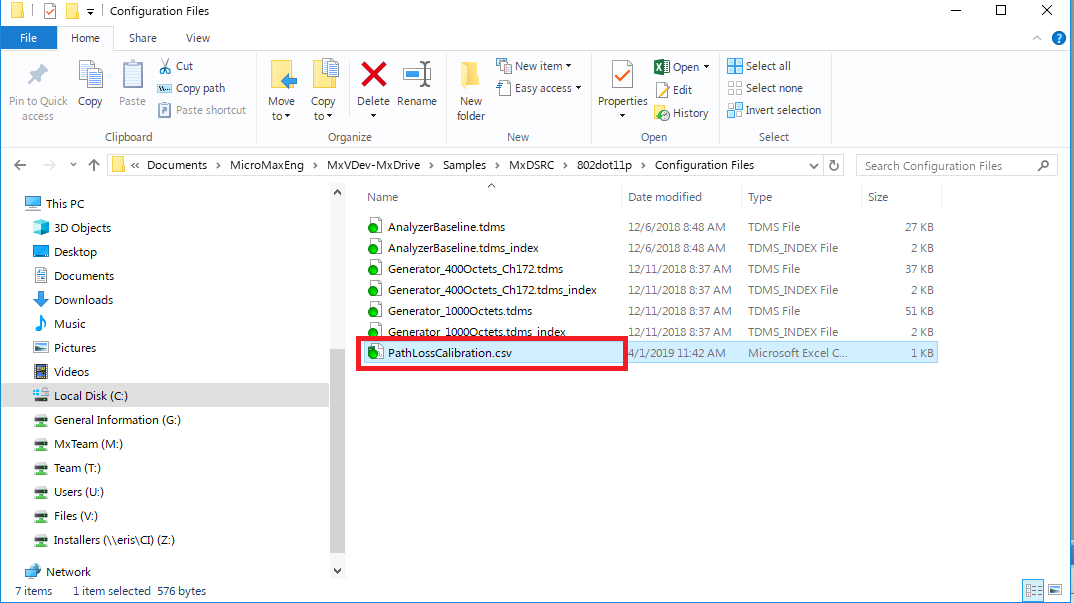
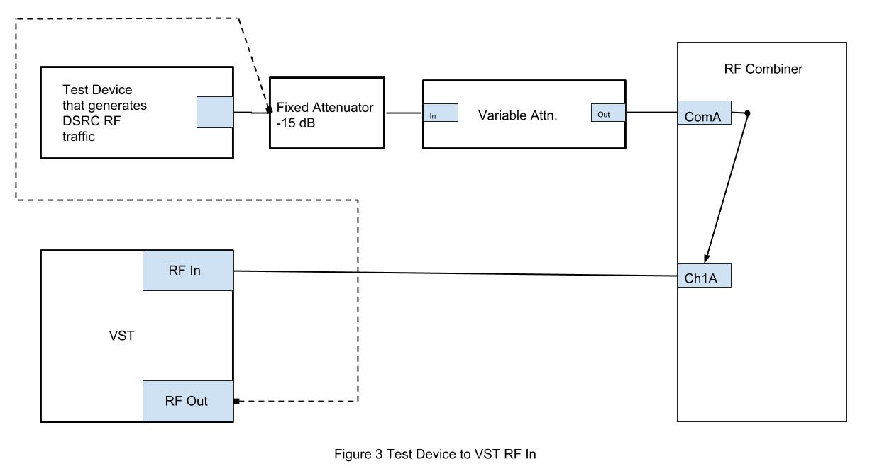
Path Losses are the total losses in a path which includes cable loss, attenuation used, insertion loss and connector loss. There are four path losses to be considered: 1.VST RF OUT to SUT 2.Test Device to SUT 3.Test Device to VST RF IN 4.SUT to VST RF IN Determination of Path LossesPath losses are calculated outside of the MxSuite environment using WLAN Suite from NI, which includes WLAN Generator, WLAN Analyzer, and NI Switch Soft Panel. WLAN Suite requires tdms configuration files to be loaded. The settings for the WLAN Analysis tool can be loaded from the AnalyzerBaseline.tdms file and those for the WLAN Generator tool can be loaded from Generator_400Octets_Ch172.tdms located in <Project Folder>\Configuration Files. Using these tdms files avoids the need to manually configure the tools. To avoid errors while loading AnalyzerBaseline.tdms, uncheck the ‘Load Waveform’ option in the load configuration file dialog box. In the event that the ‘Device Identifier is not valid’ error is thrown, select the appropriate device from the drop-down list in Resource Name parameter. The procedure followed to calculate losses is detailed below. The losses for each path should be determined for every channel (172, 174 etc). The losses determined in each path should then be entered in the file PathLossCalibration.csv located at <ProjectFolder>\Configuration Files. Enter the values from the VST Analyzer window into the appropriate columns. DO NOT change the format of the file as this might prevent the calibration values from being loaded. The Transform and the harness are provided with the DSRCPhysicalLayerTestAutomation.mxp project. Note that all the losses are negative numbers and should be entered as such. Select True or False for the SUT connected using FAKRA property.
 Click to expand.
Calibrating the Test DeviceThis configuration is used in the following tests (See 80211_TSS_TP_Test_Specification V1.1.0.pdf ): •TXT-80211-RXT-PHY-BV-02 Adjacent Channel Rejection •TXT-80211-RXT-PHY-BV-03 Non-Adjacent Channel Rejection In these tests, a DSRC Test Device is used to generate DSRC RF traffic on the specified channel. The output of the DSRC Test Device is not calibrated and therefore its output must be adjusted at the outset of these tests. The calibration of the Test Device is done through the Calibrate Modem.mxs Scenario. This scenario is executed as part of the regression file RXT BV 02 to 03.mxreg. |


The accuracies of the Vector Signal Transceiver, Programmable RF attenuator, and Combiner are included in the test system while calculating losses in the respective path.
|
|||||||||||||||||||||||||||||||||||||||||||||||||||||||||||||||||||||||||||||||||||||||||||||||||||||||||||||||||||||||||||
All IP addresses must be in the same subnet. IP addresses have this format: 192.168.xx.yyy xx must be the same for all addresses in your system. yyy must be unique for each device. There are two UDP (Generic Transform) Transforms in the test harness. For both Transforms, select the Ethernet interface from the drop down list in the Select Ethernet Interface property. Once selected, the local IP address is populated automatically. Enter the values below in the properties of the UDP Transform connected to each device.
Setting Up the Modem Proxy1.Create a folder named Danlaw in the C:\Users\Public\ directory if it is not already present. 2.Create a text file: TestSystemIPv4AddressAndPort.txt 3.In this text file, add the following two lines: Test_System_IPv4Address=192.168.xxx.yyy Test_System_ListeningPort=51000 Where 192.168.xxx.yyy is the IPv4 address of the test system. This file is used by the test system to instruct the modem proxy where to forward DSRC packets received over the air.
|

